1. Introduction
The Hingham Municipal Lighting Plant (HMLP) has put together this “Terms & Conditions and Specifications for Electric Service” handbook to present in written form the Lighting Plant’s general terms and conditions and requirements for service. This manual is in addition to, and shall be incorporated as part of HMLP’s Schedule of Rates for Electric Service. This manual is also in addition and supplementary to the applicable national, state and local electrical and safety codes. This manual does not cover items outside the Lighting Plant’s jurisdiction and should not be used as the sole source of information when requesting electric service. The Customer, in this manual, shall refer to the Customer or his contractor, electrician consultant or any person representing the Customer or performing work for him. This manual is available upon request from the Lighting Plant at either location: 31 Bare Cove Park Dr. It is also available online at www.hmlp.com.
Print
2. Application for Service
Each prospective Customer desiring electric service shall be required to complete an Application for Electric Service either online at hmlp.com or at our business office at Hingham Municipal Lighting Plant (HMLP), 31 Bare Cove Park, Hingham, MA 02043 between the hours of 7:00 a.m. and 4:00 p.m., Monday through Thursday, and 7:00 a.m. to 1:00 p.m. on Friday, excluding holidays, or online at www.hmlp.com. Service will not be offered until all necessary information has been received from the applicant.
Print
3. Utility Authorization Number (UAN)
4. Discontinuance or Refusal of Service
HMLP may discontinue a service or refuse to connect a new service for the violation of any of its Rules and Regulations, Schedule of Rates or any of the following reasons:
- In the event of a Customer’s use of equipment in such a manner so as to adversely affect the facilities/equipment of HMLP or its service to others.
- In the event of tampering with equipment furnished and owned by HMLP.
- In the event of energy theft or any unauthorized use.
- In the event of a condition determined by HMLP to be hazardous.
- In the event the Customer does not provide and maintain for HMLP an unobstructed access to its equipment.
- In the event of a condition determined by the Town of Hingham Building Commissioner, Inspector of Wires or the Fire Department to be hazardous.
5. Right of Access to Customer's Premises
Employees of HMLP, with proper identification, shall have access to the Customer’s premises at all reasonable times for the purpose of reading meters, testing, repairing, removing or exchanging any or all equipment belonging to HMLP. In addition, it is the responsibility of the Customer to insure that access to the equipment of HMLP is not impaired or blocked. HMLP may discontinue service after reasonable notice if access to its meters or other equipment is unreasonably refused or if access is obstructed or hazardous. Please refer to Section 21: Illustrations for specific clearances for HMLP equipment.
6. Customer's Responsibility for the Property of HMLP
All meters, service connections, wires, transformers and other equipment furnished by HMLP shall be, and remain, the property of HMLP. Customers shall provide space for and exercise proper care to protect the property of HMLP on its premises, and in the event of loss or damage to the property of HMLP arising from the neglect by the Customer, the cost of the necessary repairs or replacements shall be paid by the Customer.
NOTE: Missing meters will be billed to the Customer, or their agent, in the amount of $50 plus the cost of the meter to cover administrative, equipment and installation costs. Additionally, HMLP will estimate the electricity usage for the period the meter has been missing and bill the Customer accordingly.
Print
7. Voltage Fluctuations Caused by Customer
Motors
All motors of five horsepower or less connected to HMLP lines shall normally be single-phase, and motors over five horsepower shall normally be three-phase; but the Customer should contact HMLP in advance to ascertain the applicable conditions. Single-phase motors whose capacity exceeds one-half horsepower shall normally be served at 240 volts or more, but Customer should contact HMLP in advance to ascertain the applicable conditions. All motors connected to HMLP lines shall be of a type that shall not require a starting current deemed unreasonable by the HMLP, or shall have starting devices to restrict the starting current within the limits considered reasonable by the HMLP, or both.
Service Interference
Service may be refused or withdrawn when Customer’s wiring or equipment is so designed or operated as to disturb HMLP service to other Customers.
The Customer shall not in any way interfere or tamper with the HMLP’s meters, fuses, seals, instrument transformers, or any other devices and shall exercise reasonable care to protect them from damage. Tampering is a felony punishable by fine or imprisonment, or both under the Penal Law of the Commonwealth of Massachusetts.
Increase Load
The Customer shall give the HMLP 120 days’ written advance notice of intention to materially increase their load, so that adequate facilities may be provided. Residential service in excess of 100 kW and commercial service in excess of 50 kW will not be served from single-phase facilities.
Phase Unbalanced
A Customer taking three-phase electric service shall maintain as nearly as is reasonably possible equal loading on each of the three phases at the meter. If at any time the loading on any phase exceeds the average of the load on all three phases by more than 15 percent (15%), the amount to be paid by Customer for the period within which the unbalance occurred may at the discretion of the HMLP be increased by a percentage equal to that of the unbalance in excess of 15%.
Highly Fluctuating Loads
A Customer taking service for the operation of welders, x-ray machines, electric furnaces, hoists or any other equipment having a highly fluctuating or large instantaneous load characteristic which adversely affects voltage regulation or impairs HMLP’s service to the Customer or others supplied from the same distribution system, shall remedy the condition in a manner deemed adequate by HMLP, by either:
a.installing and maintaining at their own expense the corrective equipment deemed necessary by HMLP to remedy the condition, or
b.making a cash contribution of the actual reasonable cost of any equipment installed byHMLP on its side of the point of delivery to effect such correction.
HMLP may discontinue service if the Customer fails, upon notice from HMLP, to comply with the foregoing requirements.
Welders of capacity larger than 8 kVA shall not be served from a single-phase circuit.
Welders must pay monthly at least two dollars per kVa of transformer provided as a special facilities charge which will be credited toward the monthly bill.
Print
8. Interruption of Service
9. Damage to Customer's Property
HMLP shall not be liable for normal distribution failures caused by equipment malfunctions that are weather related, caused by third parties, or the result of undetectable degradation over time. The policy of HMLP regarding damage caused to residential customer’s equipment as the result of disturbances on the HMLP distribution system is stated as follows:
- If damage to a customer’s property is the direct and sole result of the negligent action by HMLP or its employees, HMLP will, in its sole discretion, either reimburse the customer for the fair market value of the damaged property or the reasonable costs to repair the damaged property.
- If damage to a customer’s property is caused as the direct result of some action not taken by HMLP after HMLP became aware of a potential problem, and had areasonable opportunity to address and correct the problem, HMLP will reimburse the customer for the fair market value of the damaged property or the reasonable costs to repair the damaged property.
- HMLP shall not be responsible for any damage caused by lightning, surge damage that occurred due to damage to HMLP’s lines or equipment caused by adverse weather, or any other damage resulting from an Act of God.
- HMLP shall not be responsible for any damage caused, in whole or in part, by the negligence of a third-party for whom HMLP had no responsibility for or control over.
10. Notice of Trouble
11. Standby and Resale Service
The following general requirements apply to Customer generating facilities designed to operate directly connected to HMLP’s electrical system (parallel operation) and those which are designed to operate isolated from the HMLP’s system (non-parallel operation.) Requirements and specifications for various types and sizes of Customer facilities shall be obtained from HMLP prior to installation.
Standby generation (non-parallel operation) may be installed by the Customer to supply all or part of the load in the event of a service interruption. The Customer’s wiring shall be arranged so as to conform to all current NEC, NESC and other state (527 CMR 12 Current Edition) or local codes, and prohibit the interconnection of the Customer’s alternative source of supply with HMLP’s service. This will require the installation of a double-throw switch or its equivalent as approved by HMLP and the Town of Hingham Inspector of Wires.
NOTE: Precautions must be taken where alternative means of generation are employed, whether emergency or otherwise, to eliminate the possibility of electrical connections between the HMLP service and the Customer’s alternate source of supply (e.g. truck docks, etc.) The Customer must notify HMLP and provide electrical details of the generator installation and isolation from the HMLP system.
Standby generation (parallel operation) requires notification and approval of HMLP before installation begins. Prior to the installation of any auxiliary generator facilities (e.g. wind turbine, solar panels, etc.), the Customer must fill out the appropriate HMLP application to provide interconnection details and to obtain approval for the facility’s protective and synchronizing equipment arrangements.
Print
12. Point of Delivery
13. Customer Wiring Standards
14. Dig Safe
Before any excavation begins, call Dig Safe at 888-DIG-SAFE to obtain information about the existing underground facilities in any specific area.
The HMLP does not own, maintain, or locate underground services. If the Customer cannot supply the location of their service to the requesting contractor they must use the services of a professional locator at their own expense.
Print
15. Availability and Character of Electric Service
The Customer shall be responsible for operation, maintenance, replacement and renewal expenses on all Customer owned equipment. The Customer shall permit the HMLP to trim trees including the removal of limbs, to the extent that such trimming shall be reasonably necessary to prevent interference with the HMLP’s lines and equipment.
Print
16. Requirements for Scheduling Service Connections
An “Application for Electric Service” for service entrance sizes of 200amps and below and 600 volts or less must be received by the HMLP in adequate time before final inspection by the Town of Hingham Inspector of Wires. This time will vary whether primary distribution facilities are in place or not. Extending primary distribution facilities to meet Customer’s needs will require more advanced notice. The Customer shall also obtain a Utility Authorization Number as detailed in Section Three of this Guide.
Application for Service (between 200 and 1000 amps, secondary voltage)
An “Application for Electric Service” for service entrance sizes larger than 200 amps and no larger than 1000 amps and 600 volts or less must be received by the HMLP in adequate time before final inspection by the Town of Hingham Inspector of Wires. Consult HMLP as early as possible to plan the project. This time is necessary to allow HMLP to secure the necessary materials to accommodate the Customer’s request. Three-Phase services may require notification six (6) months in advance due to transformer manufacturer lead times. The Customer shall also obtain a Utility Authorization Number as detailed in Section Three of this Guide.
Application for Service (greater than 1000 amps or primary voltage)
An “Application for Electric Service” for service entrance sizes larger than 1000 amps and any primary metered service (greater than 600 volts) must be received by the HMLP in adequate time before final inspection by the Town of Hingham Inspector of Wires. Consult HMLP as early as possible to plan the project. This time is necessary to allow HMLP to secure the necessary materials to accommodate the Customer’s request. The electrical connection date will be subject to the availability of the transformer(s) and other equipment needed and having sufficient time to schedule and complete the work required (in some cases, this can be 6 months or longer). The Customer shall also obtain a Utility Authorization Number as detailed in Section Three of this Guide.
The Customer shall not base their design or planning on the assumption that primary metering will be available. Primary metering shall be considered on a case by case basis.
The Customer shall supply a load sheet for any new residential or commercial construction, or any additions to an existing structure.
The Customer shall supply a plan of the proposed project to the Engineering Manager in AutoCAD 2006 format. The provided plan will be used by HMLP to design the electrical system. The final design, along with HMLP specifications, shall be submitted to the Customer in a paper format.
HMLP will inspect all new construction during normal business hours. A 48 hour notice must be given to the HMLP to schedule the inspection. Any requested inspections or site meetings outside regular business hours will be at the Customer’s expense.
The Customer shall notify the HMLP of any increase in their electrical load. HMLP will determine whether this increase will affect other customers and decide whether to upgrade the distribution system to compensate for the increased load.
17. Overhead Services and Line Extensions
New Overhead Secondary Service from a pole in a Public Way
All cables shall be copper. NO EXCEPTIONS.
A fee of $900.00 (per pole) will be charged to the customer for a service pole in their property if the point of attachment is more than 125 feet from the pole in the public way from which the service drop will originate. Please consult HMLP for scope of work and fee amount.
The Customer shall install, own and maintain a new meter socket, service entrance cable and conduit up to the point of attachment mutually agreed to by the Customer and HMLP. HMLP will provide a 6” x .” Screw Eye as the point of attachment if a new one is needed. The Customer shall make permanent connections appropriate for an all copper service (no wire nuts, Romex connectors, etc.) at the weatherhead. HMLP will install and maintain a new overhead service drop from the utility pole to the service weatherhead. HMLP will also install a meter for the new service. In an overhead service the electric meter is the only equipment attached to the customer’s structure that is owned by HMLP. All other equipment is owned and maintained by the Customer.
The opening for the meter socket shall be between a minimum of four feet (4’) and a maximum of six feet (6’) above final grade level. Please refer to Section 21 (Metering) for more information.
HMLP will not perform any work without a Utility Authorization Number and an inspection from the Town of Hingham Inspector of Wires.
18. Underground Services and Line Extensions
New Underground Secondary Service from a pole in a Public Way
All cables shall be copper. NO EXCEPTIONS.
HMLP offers two options when a customer desires an underground service from a pole in the public way:
- HMLP will install a service pole in the Customer’s property and extend overheadservice wires from the pole in the public way to this service pole for a fee of$900.00. If ledge boring is required, the Customer will be responsible for the costof the ledge boring services. The Customer will install their underground servicefrom this new service pole as described below. HMLP will own the overheadservice wire, connections, and service pole. The Customer will own theunderground service from the connection point at the top of the service pole to thehouse.
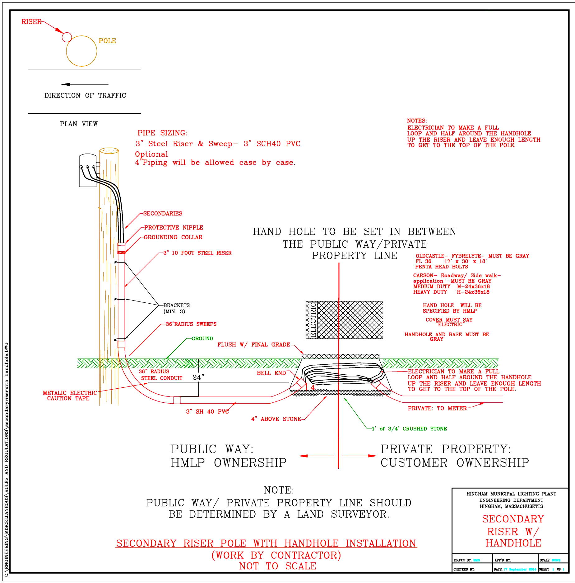
- The Customer will install their underground service from this handhole to their house. HMLP will own and maintain the secondary wires and conduits from the pole to the handhole, including the handhole and terminations inside. The customer will own and maintain the underground service from the handhole to their house. See Figure 20.
The Customer shall install, own and maintain all the conduits, cables and meter socket(s) from the service pole to the Customer’s site. The riser pipe shall be of rigid galvanized steel construction and extend twelve feet (12’) above grade level. The sweep pipe at the base of the pole attached to the riser pipe shall be of galvanized steel construction also. Please consult Town of Hingham Inspector of Wires for minimum radius requirements for service conduits. See Figure 2.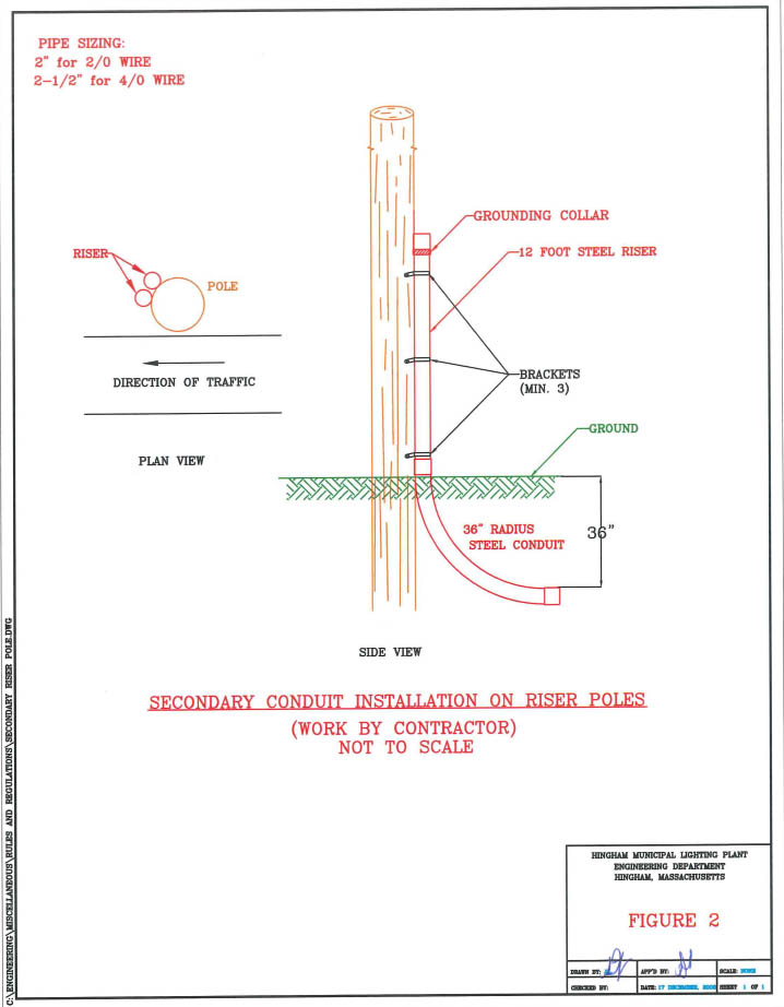
The cables shall be of enough length to extend to the top of the pole. This will allow enough slack to loop the cable through the weatherhead and make the necessary terminations at the pole.
The opening for the meter socket shall be between a minimum of four feet (4’) and a maximum of six feet (6’) above final grade level. Please refer to Section 21 (Metering) for more information.
HMLP will not perform any work without a Utility Authorization Number and an inspection from the Town of Hingham Inspector of Wires.
New Underground Primary Service from a pole in a Public Way
The Customer shall install all the conduits, handholes, vaults, cabinets and transformer bases as designed and specified by HMLP. The Customer shall also install the house service cables, conduits and meter sockets from the service handholes to the houses. HMLP will install and terminate the primary and secondary cables. HMLP will own and maintain the Primary and Secondary cables after the Customer grants HMLP an easement for the electrical system.
Note: Underground house services are owned and maintained by the Customer. HMLP owns up to terminations in the last service handhole, and the easement requested shall reflect this requirement.
HMLP will install the transformers at its own expense.
HMLP offers two options when a customer desires an underground primary service from a pole in the public way. Please consult HMLP to determine which option is best suited for the project.
- HMLP will install a service riser pole in the Customer’s property and extendoverhead primary wires from the pole in the public way to this riser pole. Thiswork will be part of the overall project and will be at the Customer’s expense.The Customer will install the underground conduits from this pole as designed by HMLP.
- The Customer, at his own expense (including street opening permit fees,) willinstall conduits from the HMLP designated pole in the public way to the variousHMLP equipment per HMLP plans and specifications. See section 20 for details.This work will be part of the overall project and will be at the Customer’sexpense.
19. Conversions to Underground Service
Customers desiring to convert their overhead electrical services to underground must contact HMLP first to determine the utility pole from which the new service will originate and whether said pole is in need of replacement prior to any conduits being attached to it. HMLP will also determine the location of the meter socket per the standards listed in metering section.
Please see Section 18 for more details.
The service cables shall be of enough length to extend to the top of the pole. This will allow enough slack to loop the cable through the weatherhead and make the necessary terminations at the pole.
All cables shall be copper. NO EXCEPTIONS.
The Customer shall install, own and maintain all the conduits, cables and meter socket(s) from the service pole to the customer’s site. The riser pipe shall be of rigid steel construction and extend twelve feet (12’) above grade level. The sweep pipe at the base of the pole attached to the riser pipe shall be of steel construction also. Please consult Town of Hingham Inspector of Wires for minimum radius requirements for service conduits.
20. Underground Construction Details
See Constructions Notes: Figure 19
All trenches shall be either undisturbed or compacted earth. No rocks larger than 2 inches in diameter shall be present in the trench base or the backfill material.
All Primary and Secondary conduits shall be 4” SCH 40 PVC encased in concrete unless otherwise specified by HMLP. HMLP requires a minimum of two conduits between its terminating points, whether primary or secondary, unless otherwise specified.
Concrete encasement shall be a minimum of three inches. The concrete shall be a minimum of 3000 PSI with 3/8” pea stone mixed in. Precautions have to be made by the contractor to prevent the conduits from floating in the concrete. The concrete shall be left to set for a minimum of Twenty-Four (24) hours before backfilling the trench.
The minimum radius for all HMLP conduit bends shall be thirty-six (36) inches. Preformed bends shall only be used on riser sweeps, and vault and pad sweeps. All other bends in the main run shall be formed by bending straight sections of conduit with a heating device. The bent conduit shall maintain its interior surface smoothness as much as possible.
The minimum depth for all conduits in the Right-of-Way shall be forty (40) inches.
Spacers shall be used to separate the conduits as shown in the illustrations at the end of this booklet. Spacers shall be installed at five (5) foot intervals along the conduit run. Conduits shall be tied to the spacers to prevent them from floating during a concrete pour.
The minimum separation between electric conduits and telephone & CATV conduits shall be twelve (12) inches vertically and twelve (12) inches horizontally. All other utilities shall have a minimum of twenty four (24) inches of separation from electric conduits. Please consult appropriate utilities for their requirements. No stacking of conduits of different utilities shall be allowed. Please refer to the illustrations at the end of this booklet. See Figure 3.
All conduits must have weatherproof measuring tape (mule tape) installed by contractor. 4” conduits must have 1800 Lb. mule tape installed. 5” and 6” conduits must have 2500 Lb. mule tape installed. Installed mule tape must be one continuous piece for each conduit for accurate measurements. Contractor must take measurements, record them on an as built plan, and provide them to HMLP. All conduits must be mandrel proofed out and witnessed by an HMLP personal.
All conduit, pad, handhole, and vault installations must be inspected by an HMLP representative before encasing in concrete or backfilling. A minimum of forty-eight (48) hours’ notice must be given for scheduling inspections.
All electric manholes, transformer pads, splice vaults, cabinets, handholes, and other electric structures shall sit on a minimum of twelve (12) inches of one and a half (1.5) inch crushed stone installed at their base. The crushed stone shall be installed on undisturbed or compacted earth. Please refer to the illustrations at the end of this booklet.
All transformer pads, splice vaults and cabinets, and other electric structures shall be located in the utility easement. The front edge of said equipment shall be a minimum of five (5) feet away from any roadways or driveways. Bollards shall be installed to protect these equipment as requested by HMLP. See Figure 18.
Conduits shall enter the single-phase transformer pads, splice vaults and cabinets from the bottom using a 45-degree bend conduit. Conduits shall only extend four (4) inches above the base of the pad, vault or cabinet. Bell ends must be installed at the ends of the conduits entering any pads, vaults or cabinets. Please refer to the illustrations at the end of this booklet. Manholes and three-phase transformer vaults have knockouts on their sides for conduit entry. See Figure 4 & 6
All transformer and switchgear pads, primary splice vaults, cabinets and manholes shall have grounding grids installed as shown in the illustrations. The grid shall consist of four (4)eight-foot-long by 5/8” diameter ground rods at each corner of the gear, joinedtogether by 2/0 bare stranded copper wire. The connections at the rods shall beMECHANICAL CLAMPS. The grounding grid shall be installed approximately two (2)feet below grade level. Enough slack shall be left inside the vault to extend two feetabove the vault surface. See Figures 5, 8 &14 depending on application.
Sweeps to riser conduits and riser conduits shall be rigid steel. One conduit shall be extended ten (10) feet up the pole with a grounding collar installed. Spare Conduit to be capped at the base of the pole. Locations of the riser conduits on pole to be decided by HMLP. See Figure 1.
HMLP shall determine the condition and suitability of a riser pole prior to any work performed by contractor
All street light circuits shall be fused and fuse devices shall be installed in the secondary handholes by the Customer. The Customer shall install the street lights, conduits and wires per HMLP specifications if the development will become a Town of Hingham accepted road. If the development will remain private, street lights will be owned and maintained by the Customer, including electricity consumption charges. See Figure 17.
Contact HMLP for street light bases. See Figure 17.
Single-Phase transformer pads shall be Nordic Fiberglass Pad, part number GS-37-43-32C:MG: 22×14, Highline Products HL374332-2224, or equivalent.
Three-Phase transformer vaults shall be Utility Precast FE-3-48 or equivalent for units up to 500 kVA, or Utility Precast FE-3-T 1000 for units above 500 kVA or equivalent.
All Transformer pads and vaults shall be installed four (4) inches above grade level.
For secondary splice handholes use:
- Carson Industries L-Series Light Duty Vault, P/N 2436-18 with LightDuty HDPE cover, P/N 2436-3B for Light Traffic areas,
- Carson Industries M-Series Medium Duty Vault, P/N 2436-18 with Medium DutyPolymer Concrete cover, P/N 2436-PC for Heavy Traffic areas.
- Or Equivalent handhole approved by HMLP.
Equivalent units from other manufacturers will be considered by HMLP if the contractor supplies HMLP with all the necessary information on the unit which shows it to be equivalent to the units shown above. All covers must say “Electric”
All secondary splice vaults shall be installed at grade level.
For above ground splicing cabinets, use Nordic Fiberglass ND-150 or equivalent for single-phase applications. Use Nordic Fiberglass ND-360 or equivalent for three-phase applications. Grounding for these cabinets shall be the same as the transformer vaults.
Telephone, CATV, and fire alarm conduits shown in “typical utility duct bank cross section” illustration are for reference purposes only. Please consult appropriate utility companies for their requirements. See Figure 3.
Quantity and location of other utility conduits on riser poles must be approved by an HMLP representative before installation. HMLP will limit the quantity of the conduits on a riser pole, usually to 4 – 4” conduits.
21. Metering
Conductors
– All service conductors shall be copper. No exceptions.
Location
– All metering equipment, including sockets and CT enclosures, shall be installed on the outside of buildings. No exceptions.
Access & Clearances
– Meter sockets must be on the front half of the building, easily accessible, and free from obstructions.
– Maintain 3 feet clearance in front and 1.5 feet on each side (3 feet total from center).
– The center of the meter socket shall be 4–6 feet above final grade.
– Maintain a minimum 3 feet separation from gas meters.
Equipment Requirements
– Residential services ≥100A must include an outside main breaker.
– Commercial services with self-contained sockets must include a bypass switch.
– Single-phase self-contained sockets shall have four (4) jaws.
Multiple Meters
– Stacked meter banks shall be reviewed case-by-case by HMLP.
– Customers must permanently label each socket with phenolic labels matching the served unit or address.
– Energization will occur only after HMLP verifies correct labeling.
Transformer-Rated Metering
– HMLP will supply the meter socket, test switch, and CTs; installation is the customer’s responsibility.
– CT-rated sockets must be as close as possible to the transformer. If not feasible, a free-standing pedestal shall be installed.
– Where transformer-mounted CTs are not possible, HMLP will specify the CT cabinet type.
– CT meter sockets must be within 20 conduit feet of CTs, with 1.25″ SCH40 PVC conduit and a continuous pull string.
Primary Metering on Customer-Owned Equipment
– For services requiring primary metering (including loads with transformers >1000 kVA or services rated 4000 amps or larger), all transformers, switchgear, conductors, and related equipment shall be installed, owned, and maintained by the customer.
– The customer is responsible for all infrastructure beyond the point of delivery, including clear access and compliance with NESC/NEC requirements.
Compliance
– Cutting an HMLP seal requires a Utility Authorization Number and inspection by the Town of Hingham Inspector of Wires.
22. Transformer/Switchgear Ownership and Maintenance
HMLP shall own and maintain transformers and switchgear only for services requiring equipment up to and including 1000 kVA and less than 4000 amps.
For any service requiring a transformer greater than 1000 kVA, or service rated 4000 amps or larger, the customer shall install, own, and maintain all related infrastructure, including transformers, switchgear, conductors, and associated equipment. Service rated 4000 amps or larger shall be primary metered.
If a customer requests transfer of ownership for equipment 1000 kVA or less or 3000 amps or less, such transfer may be considered by HMLP, provided the customer, at their own expense, rebuilds the infrastructure to meet current HMLP standards.
No transfer of ownership will be permitted for equipment greater than 1000 kVA or exceeding 3000 amps.
23. Easements
24. Town of Hingham Inspector of Wires
25. Customer Alteration of Grade
26. Additional Electrical Load to an Existing Service
27. Non Standard Service
The Customer shall pay the cost of any special installation necessary to meet his peculiar requirements for service at other than standard voltages, or for the supply of closer voltage regulation than required by standard practice, in HMLP’s case +/- 5%.
Print
28. Temporary Service
An installation charge, or hook up fee, of $200.00 shall be made for each temporary overhead or underground single-phase service connection, if consisting only of service wires and a self-contained meter in case of overhead services and a self-contained meter in case of underground services. When more than the above is required to provide the requested temporary service, the Customer shall pay for all work done by HMLP in completing, and removing, the temporary extension of existing electric lines and facilities needed to provide the temporary service requested. HMLP will provide the Customer with a cost estimate for non-standard temporary services. The temporary extension charge shall be a non recoverable charge and payable in advance of any construction. It should be noted that the above fee is in addition to the deposit fee detailed in the HMLP Rate Schedule handbook.
Conversion of Temporary Service to a Permanent One:
When the temporary service is for a building contractor and service may be furnished later on a permanent basis, material in the temporary service may be used in the permanent connection. Any material and associated labor proposed to be used in the permanent connection will not be considered in determining the installation charge for the temporary service.
Print
30. Scope
31. Revisions
32. Illustrations
Figure 1 Primary Riser Conduit Installation
Figure 2 Secondary Riser Conduit Installation
Figure 3 Typical Utility Duct bank Cross Section
Figure 4 Typical Single-Phase Transformer Pad and Splice Vault Installation
Figure 5 Typical Single-Phase Transformer Pad and Splice Vault Ground Grid
Figure 6 Three-Phase Transformer Vault (Up to 500 kVA)
Figure 7 Three-Phase Transformer Vault (Larger than 500 kVA)
Figure 8 Three-Phase Transformer Vault Ground Grid
Figure 9 Pedestal Mounted Self-contained Meter Socket Installation
Figure 10 Pedestal Mounted CT Rated Meter Socket
Figure 11 House Mounted Meter Socket – Overhead Service
Figure 12 House Mounted Meter Socket – Underground Service
Figure 13 Primary Manhole
Figure 14 Primary Manhole – Grounding Grid
Figure 15 Primary Manhole Frame and Ring Detail
Figure 16 26” Primary Manhole Cover
Figure 17 Street Light Pole and Base Installation
Figure 18 Bollards
Figure 19 Construction Notes